
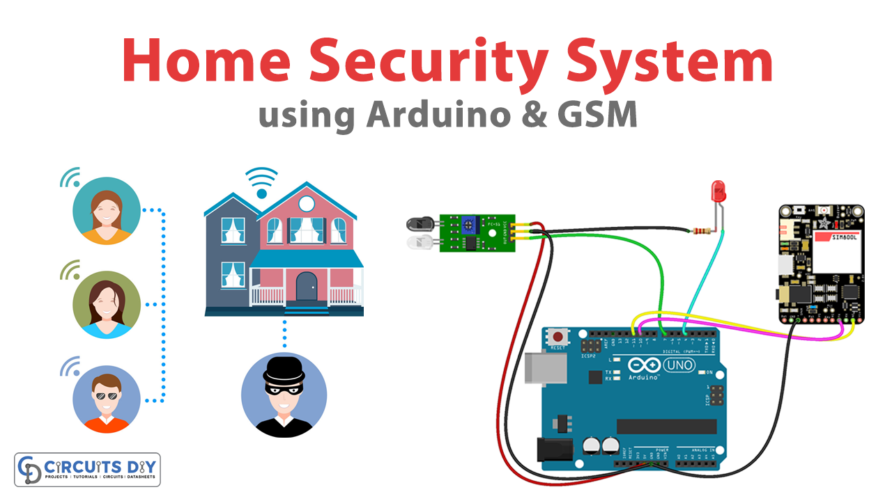
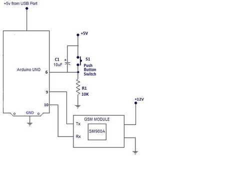
Arduino Home Security System 7 Steps with Pictures Circuit Diagram After testing our circuit now it's time to make hardware for Arduino based home Security System. The figure below is the circuit Diagram of security system for home using Arduino and sensors.
The security system can dial up to two phone numbers to alert you. It can also send text message to one of the numbers. Circuit and working Fig. 1 shows circuit diagram of the Arduino based GSM home security system. It works off a 12V power supply (connected across CON2). An Arduino microcontroller (MCU) requires only 5V but a GSM modem Today, we will design a Proteus simulation of Smart Home Security System using Arduino, we will also design Arduino Code.
Arduino security alarm system Circuit Diagram
You can check out our Fingerprint door lock system using Arduino. Do you know how a PIR sensor works with Arduino, if not please check it out first? Also, read our E-book on Arduino to make 10+ projects with well-labeled circuit diagrams. Complete the circuit and upload the given code to use the security system. Feeling handy? Build your own GSM home security system with Arduino! Learn about components, connections, and how to trigger alerts on your phone. Keep your home safe on a budget!

This project will detect any intruders and alarm you using the components of an LED, a buzzer, ultrasonic sensor, and a LCD display.
Arduino Home Security System Circuit Diagram
Arduino Based GSM Home Security System: This project is designed using normally-closed reed switches connected to doors and windows and additional passive infrared (PIR) motion sensors to detect movement of a burglar or an unwanted intruder in your home. The security system can dial up to…
